https://dronebotworkshop.com/sd-card-arduino/
SD Card Experiments with Arduino | DroneBot Workshop
SD and microSD cards are a simple way to add huge amounts of non-volatile storage to your Arduino designs. In this article, I will show you how to use SD card modules with the Arduino.
dronebotworkshop.com
Introduction
Secure Digital, or SD, Cards are used in a variety of applications. You likely have several of them in your electronic devices as they are used in phones, tablets, cameras, and music players.
The Raspberry Pi also uses a microSD card for storage, in a sense it performs the function of a hard drive.
Anywhere that you need a large amount of inexpensive, non-volatile memory an SD (or microSD) card is a good choice. And, as you are about to see, these cards are very easy to use in your Arduino projects.
SD and microSD Cards
The SD card was developed as a joint effort between SanDisk, Panasonic, and Toshiba. The first SD cards were released in August 1999. In January 2000 the three companies formed the SD Association to create standards for SD cards.
There are actually three sizes of SD cards – standard SD cards, miniSD cards, and microSD cards. The miniSD card was never that popular and hasn’t been produced since 2008 so modern devices make use of either standard SD cards or microSD cards.
There are also a number of designations on SD cards such as “SDXC”, SDUC”, “UHS-I”, “Class 10” etc. This can get a bit confusing when trying to choose an SD card.
The following is an (admittedly lame) attempt to clarify some of this!
File Systems
SD Cards have evolved to use different file systems, different speeds, and different connection methods than the original 1999 design. These differences are designated into five different storage classes:
- SD or SDSC – Standard Capacity SD cards. These use the FAT32 file system and can store up to 2 GB of data. Older cards used the FAT16 file system.
- SDHC – These are High Capacity cards. They also use the FAT32 file systems and can store from 2 GB to 32 GB of data.
- SDXC – These are Extended Capacity cards. They use the exFAT file system and have capacities from 32 GB to 2 TB.
- SDUC – These are Ultra Capacity cards. They have capacities from 2 TB to a whopping 128 TB.
- SDIO – This is a standard that combines memory cards with Bluetooth and other wireless networking standards, allowing the cards to be read remotely.
Speed
SD cards are serial data cards and thus have limits to the speed that they can transfer data. As SD cards evolved so has their speeds and there are new designations to determine which cards are faster than others.
Older cards used a Class designation from 1 to 10, with a 10 being the fastest. Modern SD cards can all exceed Class 10 speed so the class designation is virtually meaningless.
SDHC and SDXC cards can use an Ultra High-Speed bus and have the following designations:
- UHS-I – Transfers data at a rate of 50 MBps to 104 MBps.
- UHS-II – Transfers data at a rate of 156 MBps.
- UHS-III – Transfers data from 312 MBps to 624 MBps.
There is also a new specification called “SD Express” which can transfer data at up to 985 MBps.
Electrical Connections
A standard SD card uses the SPI bus and works at 3.3 volts. SDHC and SDXC cards can also switch to the “one-bit SD bus” and in this mode they work on 1.8 volts.
When an SDHC or SDXC card is inserted into its socket it will initially use the SPI bus. The host computer can switch the device to one-bit mode if the device supports it.
SD cards and microSD cards are electrically compatible, however, they do not use the same pinouts. The plastic “SD Adapter” that is usually included with microSD cards is wired to reconfigure the pinout so the microSD card can also be used in an SD card slot.
SD Card Modules for Arduino
There are many SD card modules available for the Arduino. Some of them are stand-alone, others are shields. Many of the shields also have additional components like real time clocks, Ethernet adapters and temperature sensors integrated along with the SD card holder.
In the experiments I’ll be performing I used a microSD card adapter, however you can substitute a shield of full-sized SD card adapter if you wish.
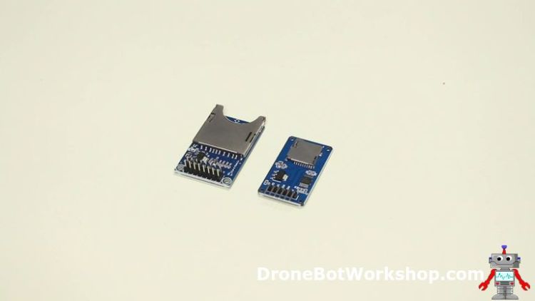
Standard SD Modules
The full-sized SD card modules I’ve used have SPI bus connections and connections for either a 5-volt or 3.3-volt power supply.
The SD card uses 3.3-volt logic so there is a built-in voltage regulator to reduce the 5-volt supply to 3.3-volts. If you use a 3.3-volt supply the regulator is bypassed.
One thing to note is that many of these modules do not have logic-level converters and therefore expect that 3.3-volt logic will be used. If you are using 5-volt logic, as with an Arduino Uno or Mega, you’ll need to supply logic-level converters or use a resistor array to work with the 3.3-volt logic.
microSD Modules
In my experiments I elected to use the microSD module, the one I’m using is very common.
These modules are made to be used with 5-volt logic as they contain built-in logic converters, as well as voltage regulators. As such they have only a 5-volt power input.
Using SD Cards with Arduino
The Arduino does not have a particularly fast bus so any type of SD card will work well with it.
I’ll be showing you the connections using a microSD module but they are pretty well identical for a full-sized SD module. Remember though that if you elect to use a full-sized module you may need to do some logic-level conversion, otherwise your data will be garbled.
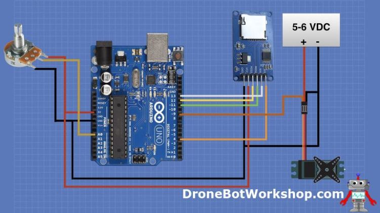
Hooking up the microSD Module
The following diagram shows how to hoo the microSD card module to the Arduino Uno, using the SPI bus.
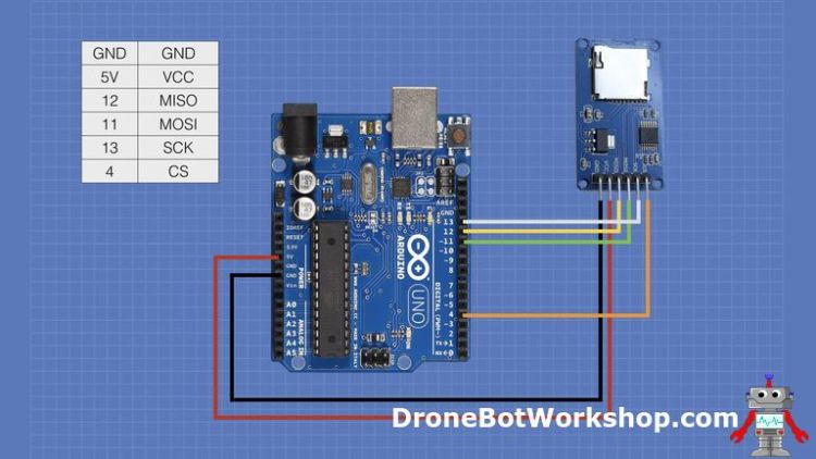
If you are using a shield with an SD or microSD card you might need to change the Chip Select (CS) pin connection, the one I have connected to pin 4. Some shields use pin 6 or pin 10, check with your shield manufacturer or use a multimeter to determine if this is the case with your shield
If you are using an Arduino Mega the SPI pin connections are different. The following table shows the relationship between the Uno and the Mega.
| SPI Bus Connect | Arduino Uno | Arduino Mega |
| MISO | 12 | 50 |
| MOSI | 11 | 51 |
| SCK | 13 | 52 |
| CS | 4 (can be another pin) | 53 (can be another pin) |
Again note that you can use almost any pin for Chip Select (CS), so if you do change it just remember to change the appropriate line in the sketch to reflect the difference.
Arduino SD Library
The Arduino IDE already has a library for working with SD cards. It supports both FAT16 and FAT32 file systems on both standard SD (SDSC) or SDHC cards. Keep that in mind if you are reformatting your microSD card and don’t use exFAT.
Another thing to remember is it uses the older 8.3 naming convention for file names, so keep your names down to 8-characters or less with a maximum 3-character extension. A name like “TESTFILE.TXT” is great, one like “MYNICEFILE.FILE” won’t work.
You can also use forward slashes (“/”) to specify directories if you need to.
The Arduino also has the SPI Library for communicating over the SPI bus, you’ll need that to talk to your SD or microSD card module.
Arduino Example Sketches
The Arduino SD Library has a number of example sketches included with it, and they are great for learning how to work with an SD card.
You can access these libraries by opening the File menu and selecting Examples. From the sub-menu scroll down until you get to the SD entry and highlight that. You’ll see six example sketches that you can try.
We will look at a few of them now.
ReadWrite
The first example we will look at is the ReadWrite example. As its name would imply it shows you how to read and write data from an SD card.
/*
  SD card read/write

 This example shows how to read and write data to and from an SD card file
 The circuit:
 * SD card attached to SPI bus as follows:
 ** MOSI - pin 11
 ** MISO - pin 12
 ** CLK - pin 13
 ** CS - pin 4 (for MKRZero SD: SDCARD_SS_PIN)

 created   Nov 2010
 by David A. Mellis
 modified 9 Apr 2012
 by Tom Igoe

 This example code is in the public domain.

 */

#include <SPI.h>
#include <SD.h>

File myFile;

void setup() {
  // Open serial communications and wait for port to open:
  Serial.begin(9600);
  while (!Serial) {
    ; // wait for serial port to connect. Needed for native USB port only
  }


  Serial.print("Initializing SD card...");

  if (!SD.begin(4)) {
    Serial.println("initialization failed!");
    while (1);
  }
  Serial.println("initialization done.");

  // open the file. note that only one file can be open at a time,
  // so you have to close this one before opening another.
  myFile = SD.open("test.txt", FILE_WRITE);

  // if the file opened okay, write to it:
  if (myFile) {
    Serial.print("Writing to test.txt...");
    myFile.println("testing 1, 2, 3.");
    // close the file:
    myFile.close();
    Serial.println("done.");
  } else {
    // if the file didn't open, print an error:
    Serial.println("error opening test.txt");
  }

  // re-open the file for reading:
  myFile = SD.open("test.txt");
  if (myFile) {
    Serial.println("test.txt:");

    // read from the file until there's nothing else in it:
    while (myFile.available()) {
      Serial.write(myFile.read());
    }
    // close the file:
    myFile.close();
  } else {
    // if the file didn't open, print an error:
    Serial.println("error opening test.txt");
  }
}

void loop() {
  // nothing happens after setup
}
The sketch starts by including both the SPI and SD libraries. We then define a File object called myfile.
The whole sketch runs in the setup, so it runs once and then ends.
In the Setup we set the speed for the serial monitor and then write “Initializing SD card…” to it. We then initialize the SD card and print an error message if it fails.
Note the line with SD.begin(4) in it. The number “4” is the pin that the Chip Select (CS) of the module is connected to. If you’re using a shield which uses a different pin you’ll need to change this line to the proper value.
Assuming that the card is OK we then open a file. Take a good look at this statement as it is key to understanding how to work with the file system.
The SD.open opens the file. We specify the file name and then we add the FILE_WRITE parameter to indicate that we want to write to the file. If we hadn’t specified that the file would be open to read instead.
If the file does not exist it will be created and opened. If it already exists then it will be opened and any text we add wil be appended to it. This is an important point to note.
We write to the serial monitor and then use myFile.println to write to the file itself.
After that we close the file. Again, this is an important point to note when working with files, you need to close them when you are done with them.
After we write to the file we open it again, this time to read from it. Note that this time we only need to specify the file name.
Compile the sketch and send it to your Arduino, make sure that you have a microSD card in your module and that it is formatted with the FAT32 file system. Then open your serial monitor.
You should see the text “testing 1, 2, 3.” displayed on the screen.
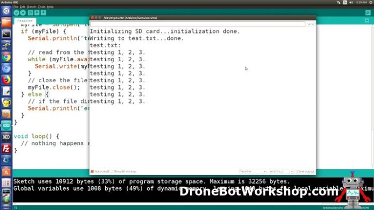
Try pressing the reset button on your Arduino and observe the serial monitor. You should see an additional line of text every time you press the button. This is because the sketch is appending the text to the file every time it is run.
DataLogger
A Datalogger is a device that can record data over a period of time. It can be used to observe trends or just to record data.
The SD library has a simple Datalogger example. Unlike a professional datalogger, this one does not use a real time clock to add a timestamp to the data, it simply reads the data and writes it to a file on the SD card.
To use this sketch you will need to add some additional components to the circuit, specifically three potentiometers. These should be linear taper devices, any value from 5k up would work – I used three 10k pots in my setup.
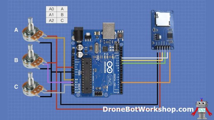
The wiper of each potentiometer is connected to one of the Arduino analog input pins, A0, A1, and A2. One side of each pot is connected to the 5-volt output, the other side is connected to ground.
This will allow you to vary the voltage sent to the analog pins from zero to 5 volts. We will measure the voltage and write the value, from 0 to 1023, to the SD card. The results will be saved in a comma-delimited file.
/*
  SD card datalogger

 This example shows how to log data from three analog sensors
 to an SD card using the SD library.

 The circuit:
 * analog sensors on analog ins 0, 1, and 2
 * SD card attached to SPI bus as follows:
 ** MOSI - pin 11
 ** MISO - pin 12
 ** CLK - pin 13
 ** CS - pin 4 (for MKRZero SD: SDCARD_SS_PIN)

 created  24 Nov 2010
 modified 9 Apr 2012
 by Tom Igoe

 This example code is in the public domain.

 */

#include <SPI.h>
#include <SD.h>

const int chipSelect = 4;

void setup() {
  // Open serial communications and wait for port to open:
  Serial.begin(9600);
  while (!Serial) {
    ; // wait for serial port to connect. Needed for native USB port only
  }


  Serial.print("Initializing SD card...");

  // see if the card is present and can be initialized:
  if (!SD.begin(chipSelect)) {
    Serial.println("Card failed, or not present");
    // don't do anything more:
    while (1);
  }
  Serial.println("card initialized.");
}

void loop() {
  // make a string for assembling the data to log:
  String dataString = "";

  // read three sensors and append to the string:
  for (int analogPin = 0; analogPin < 3; analogPin++) {
    int sensor = analogRead(analogPin);
    dataString += String(sensor);
    if (analogPin < 2) {
      dataString += ",";
    }
  }

  // open the file. note that only one file can be open at a time,
  // so you have to close this one before opening another.
  File dataFile = SD.open("datalog.txt", FILE_WRITE);

  // if the file is available, write to it:
  if (dataFile) {
    dataFile.println(dataString);
    dataFile.close();
    // print to the serial port too:
    Serial.println(dataString);
  }
  // if the file isn't open, pop up an error:
  else {
    Serial.println("error opening datalog.txt");
  }
}
The Datalogger sketch starts off in a similar fashion to the previous example. You’ll note that a constant named chipSelect is assigned to the pin you are using to connect to the CD line on your module. Again, if you are using a shield that connects CS to a different pin you’ll need to adjust that accordingly.
Unlike the last sketch this one operates in the Loop, which makes sense as it will continually read the value of the voltages on the three analog inputs and write them to the file.
The section that reads the sensors is a nice example of efficient programming. Instead of writing a line for each sensor a for loop is used to step through the sensors and to format the text for the comma-delimited text file. You can easily extend this to use more analog ports.
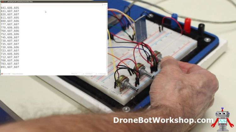
Load the sketch to your Arduino and open your serial monitor. You will see the values of the three analog inputs displayed, adjust some of the potentiometers and observe how they change.
After running it for a while power down the Arduino and remove the card. Now insert the card into your computer and read the resulting file. You should see it contains the same data you observed on the serial monitor.
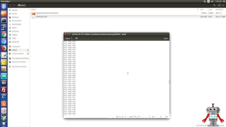
As this is a comma-delimited text file you can also open it up using your preferred spreadsheet and read the data in columns.
DumpFile
Reading the file on your computer is useful but not as convenient as using the Arduino to do it. The final example we will take a look at will read the file to the Arduino serial monitor.
/*
  SD card file dump

 This example shows how to read a file from the SD card using the
 SD library and send it over the serial port.

 The circuit:
 * SD card attached to SPI bus as follows:
 ** MOSI - pin 11
 ** MISO - pin 12
 ** CLK - pin 13
 ** CS - pin 4 (for MKRZero SD: SDCARD_SS_PIN)

 created  22 December 2010
 by Limor Fried
 modified 9 Apr 2012
 by Tom Igoe

 This example code is in the public domain.

 */

#include <SPI.h>
#include <SD.h>

const int chipSelect = 4;

void setup() {
  // Open serial communications and wait for port to open:
  Serial.begin(9600);
  while (!Serial) {
    ; // wait for serial port to connect. Needed for native USB port only
  }


  Serial.print("Initializing SD card...");

  // see if the card is present and can be initialized:
  if (!SD.begin(chipSelect)) {
    Serial.println("Card failed, or not present");
    // don't do anything more:
    while (1);
  }
  Serial.println("card initialized.");

  // open the file. note that only one file can be open at a time,
  // so you have to close this one before opening another.
  File dataFile = SD.open("datalog.txt");

  // if the file is available, write to it:
  if (dataFile) {
    while (dataFile.available()) {
      Serial.write(dataFile.read());
    }
    dataFile.close();
  }
  // if the file isn't open, pop up an error:
  else {
    Serial.println("error opening datalog.txt");
  }
}

void loop() {
}
The DumpFile sketch dumps the contents of the file on the SD card to the serial monitor. As with the first example it works entirely in the Setup routine so there is no code in the loop.
After opening the file for reading the sketch uses a while statement to read the data line-by-line while it is available. Each line is printed to the serial monitor.
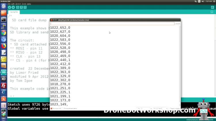
Run the sketch and open the serial monitor. You should observe the same data you saw in the serial monitor when you initially ran the Datalogger sketch.
Servo Motor Recorder & Playback
So now that we have looked at some of the SD card example sketches let’s write one of our own.
The sketches I’m about to show you will allow you to record the position of a servo motor and then play it back. Essentially I’ve combined parts of the Datalogger and DumpFile sketches with a simple servo driver.
You can use this sketch as-is or, better yet, expand upon it to record and playback movements on a robot arm, a robot car or you can use it to create a sequence that plays back on one or more LEDs.
Although I’m only controlling one servo motor in this example it would be very simple to add more of them.
Arduino Hookup
If you still have the Datalogger circuit hooked up on your breadboard you can leave it as it is, we will only be using the potentiometer connected to pin A0. Otherwise, you’ll need one potentiometer that is hooked up as follows.
You will also need a servo motor, along with a power supply for that motor. Although you could hook the servo up to the Arduino 5-volt output I really don’t recommend it, as sharing a servo with the Arduino power supply isn’t a very good idea – it can induce noise and voltage drops onto the supply lines.
I used my bench power supply for the external 5-volt supply, you could also use a 6-volt battery if you wish.
I used a common SG90 servo motor for this test but you can use pretty well any servo you happen to have on hand.
Servo Recorder
I’ve created two sketches, one that records the servo data onto the SD card and a second one that plays it back. You could expand upon them and include them both in the same sketch, perhaps with some record and playback pushbuttons.
/*
  Servo position recorder
  servo-record.ino
  Records servo movements on SD card
  Displays results on Serial Monitor
  DroneBot Workshop 2019
  https://dronebotworkshop.com
*/

// Include libraries

#include <SPI.h>
#include <SD.h>
#include <Servo.h>

// CS pin for SD Card Module
const int chipSelect = 4;
// Analog pin for potentiometer
int analogPin = 0;
// Integer to hold potentiometer value
int val = 0;

// Create a Servo object
Servo myservo;

void setup() {

  // Open serial communications and wait for port to open:
  Serial.begin(9600);
  while (!Serial) {
    ; // wait for serial port to connect. Needed for native USB port only
  }


  Serial.print("Initializing SD card...");

  // see if the card is present and can be initialized:
  if (!SD.begin(chipSelect)) {
    Serial.println("Card failed, or not present");
    // don't do anything more:
    while (1);
  }
  Serial.println("card initialized.");

  // Attach servo on pin 9 to the servo object
  myservo.attach(9);
}

void loop() {
  // make a string for assembling the data to log:
	String dataString = "";

  // Read pot value and append to the string
  // Map to range of 0-180 for servo
    val = map(analogRead(analogPin), 0, 1023, 0, 180);
    dataString += String(val);

  // Write to the servo
  // Delay to allow servo to settle in position
	myservo.write(val);
	delay(15);


  // open the file. note that only one file can be open at a time,
  // so you have to close this one before opening another.
  File dataFile = SD.open("servopos.txt", FILE_WRITE);

  // if the file is available, write to it:
  if (dataFile) {
    dataFile.println(dataString);
    dataFile.close();
    // print to the serial port too:
    Serial.println(dataString);
  }
  // if the file isn't open, pop up an error:
  else {
    Serial.println("error opening servopos.txt");
  }
}
The sketch starts by including libraries for the SPI bus, the SD card module and for the servo motor. All three libraries are part of your Arduino IDE so you don’t need to install anything.
Once again if your SD card is on a shield you might need to change the chipSelect constant value to match.
I also define integers to hold the analog input pin number and to hold the value read from that pin.
Finally, an object called myservo is created to represent the servo motor.
The Setup contains code we have seen before with the addition of a line to set up the servo motor and attach it to pin 9. You can use a different pin if you want to, just make sure that it is a pin that supports PWM.
The Loop works in a similar fashion to the Datalogger, except in this case only one analog input is read.
Pay attention to the line that reads the analog input value. It uses a Map function to change the range of the input from 0 to 1023 to a range of 0 to 180, which is what the servo requires.
We then send this value to the servo motor to position it. A small time delay is added to allow the servo to move into place and settle.
Lastly we write the same value to the file on the SD card. It is also pointed to the serial monitor so you can observe it in action.
Then we repeat the Loop again.
Run the sketch and put your servo through its paces. Then stop it and move on to the next sketch, the one that will play back the motions you just recorded.
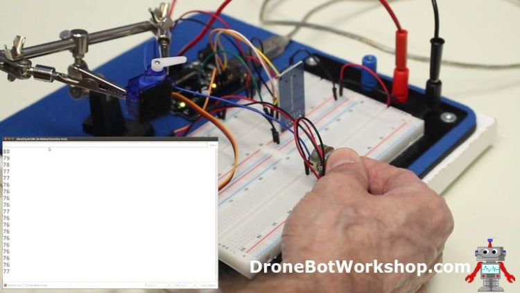
Servo Playback
The servo playback sketch will read the file we created and playback the servo motor movements.
/*
  Servo position playback
  servo-playback.ino
  Plays back servo movements from SD card
  Used with servo-record.ino
  Displays results on Serial Monitor
  DroneBot Workshop 2019
  https://dronebotworkshop.com
*/

// Include libraries

#include <SPI.h>
#include <SD.h>
#include <Servo.h>

// CS pin for SD Card Module
const int chipSelect = 4;

// String to hold one line of text
String buffer;

// Create a Servo object
Servo myservo;

void setup() {

  // Open serial communications and wait for port to open:
  Serial.begin(9600);
  while (!Serial) {
    ; // wait for serial port to connect. Needed for native USB port only
  }

  Serial.print("Initializing SD card...");

  // see if the card is present and can be initialized:
  if (!SD.begin(chipSelect)) {
    Serial.println("Card failed, or not present");
    // don't do anything more:
    while (1);
  }
  Serial.println("card initialized.");

  // Attach servo on pin 9 to the servo object
  myservo.attach(9);

  // open the file. note that only one file can be open at a time,
  // so you have to close this one before opening another.
  File dataFile = SD.open("servopos.txt");


  // If the file is available, read it
  if (dataFile) {
    while (dataFile.available()) {
    // Write one line to buffer
    buffer = dataFile.readStringUntil('\n');
    // Print to serial monitor
      Serial.println(buffer);
    // Convert string to integer and position servo
      myservo.write(buffer.toInt());
    delay(15);

    }
    dataFile.close();
  }
  // if the file isn't open, pop up an error:
  else {
    Serial.println("error opening servopos.txt");
  }
}

void loop() {
}
The sketch starts identically to the previous one with the addition of a string variable called buffer. This variable will hold one line of text from the file.
All of the action for this sketch is contained in the Setup routine, so the sketch will run once and move the motor and then it will stop. If you wish you can move some of the sketch into the loop so that the servo repeats the recorded motions indefinitely.
The file is opened for reading and then it is read, one line at a time. We accomplish this in the line buffer = dataFile.readStringUntil(‘\n’) . This will read the file until it encounters a NewLine character, which is inserted into the file after each line.
We then print the line value to the serial monitor.
After that we use the value to set the servo motor position. Note that since the line is a string we need to convert it to an integer so that the servo object can use it. The toInt() parameter accomplishes this for us.
Once again we delay the servo after each reading to give it a chance to move into position.
We then close the file.
Run this and observe the servo motor motion, it should be identical to the motion you initially recorded.
Conclusion
As you can see it is very simple to incorporate SD cards and microSD cards into your Arduino designs. By using them you can add a huge amount of non-volatile storage to your projects.
Hopefully this has inspired you to start using these versatile devices yourself and make some beautiful memories of your own!
Resources
Code from this article – The record and playback code, inconvenient ZIP file.
SD Association – The SD Association, the people who set the standards for SD cards and all of their derivative form factors.
'사물인터넷' 카테고리의 다른 글
| Using OLED Displays with (0) | 2021.07.04 |
|---|---|
| Control Large DC Gearmotors with PWM & Arduino (0) | 2021.07.04 |
| Using a Real Time Clock with Arduino (0) | 2021.07.04 |
| Using Rotary Encoders with Arduino (0) | 2021.07.04 |
| Build a Digital Level with MPU-6050 and Arduino (0) | 2021.07.04 |


