출처: https://dronebotworkshop.com/shift-registers/
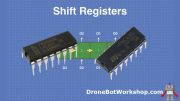
Shift Registers - 74HC595 & 74HC165 with Arduino
Learn to use the 74HC595 and 74HC156 shift registers to add extra input and output ports to your Arduino, then use them to build a fancy LED light display!
dronebotworkshop.com
I’ve got a few shifty characters with me today but don’t worry, I’ll show you how to control them and expand the capabilities of your Arduino. And, as a bonus, we’ll build a fancy LED light display.
Introduction
Today we will work with a couple of basic electronics “building blocks”, shift registers. These handy devices are used for all sorts of purposes like data conversion, buffering and storage, but today we will be seeing how they can also be used to expand the number of digital I/O ports on an Arduino or other microcontrollers.
By learning to use shift registers you’ll be adding another handy tool to your designers’ toolkit.
Expand your Arduino
Arduino’s have a number of digital I/O ports already, in fact, the Arduino Mega 250 boasts 54 digital I/O pins plus another 16 analog inputs that can double as digital I/O pins. So with 70 potential I/O pins you don’t usually have a need for more.
But sometimes you actually do need more.
Take the familiar “LED Cube”. A cube with a 4x4x4 dimension would require 64 LEDs, within the capability of an Arduino Mega 2560 if you “borrow” a few analog pins. But you’re nearly at the limit.
If you wanted to expand to a 5x5x5 cube then you’re out of luck, you’ll need 125 LEDs for that and you can’t control them individually with one Arduino.
Even a 4x4x4 cube using standard (i.e. non-addressable) RGB LEDs would put you past the limit.
There are many ways to solve these issues, including running the LEDs ina matrix or using a shift register. The shift register will allow you to address a large number of LEDs using only a few Arduino I/O pins.
There are other times when you have a lot of sensors, displays or other I/O devices and can’t spare a lot of pins for LEDs or switches, but you need a multi-LED display or a small keypad. Again shift registers can come to the rescue.
Let’s examine these handy devices.
Shift Registers
Shift Registers are sequential logic circuits that are used for the conversion, storage or transfer of binary data.
These devices are used to convert between serial and parallel data. They can be used in data communications circuits as well as memory and buffer circuits. Many complex electronic circuits, such as microprocessors and microcontrollers, use shift registers internally.
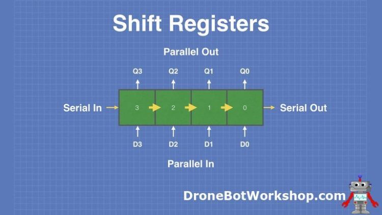
Types of Shift Registers
Shift registers deal with both serial and parallel data on both their inputs and outputs and they can convert between these formats.
There are four basic types of shift registers:
Serial In – Parallel Out
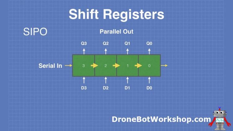
The Serial In – Parallel Out (SIPO) shift register converts serial data to parallel data. It is used in communications and to drive multiple output ports using serial data.
Parallel In – Serial Out
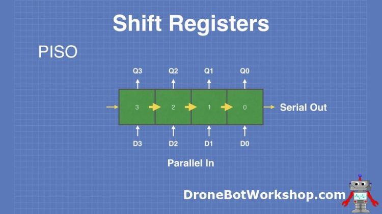
The Parallel In – Serial Out (PISO) shift register converts parallel data to serial data. It is used in communications and to convert multiple input ports to serial data.
Parallel In – Parallel Out & Serial In – Serial Out

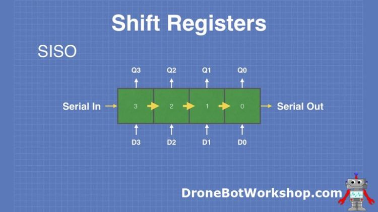
You might find these two strange. Why would you want a shift register that outputs data in the same format that it was input?
The answer is that this can be used as a buffer, to hold data for a specific number of clock cycles. The shift registers we are using today both employ similar buffers to hold data on tehi=r inputs and outputs so it doesn’t change while the register is being shifted through.
How Shift Registers work
Internally shift registers consist of a number of basic logic gates, many arranged as “flip flops”.
If you aren’t familiar with a flip-flop it is a basic electronic circuit that can act to hold the value of data from its input. It is a fundamental building block and is used everywhere, including in many forms of memory circuitry.
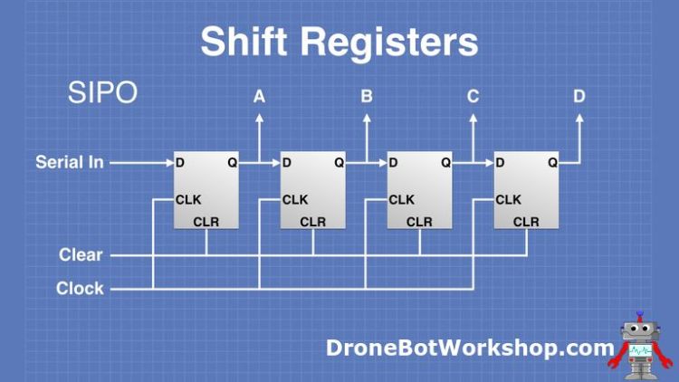
A Serial In – Parallel Out, or SIPO, register uses a series of flip-flops, one for each bit on the parallel output. The illustrations here show a 4-bit device.
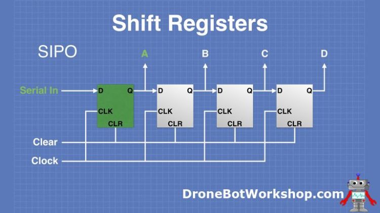
As the first bit of serial data is clocked in it is stored in the flip-flop and appears on its output.
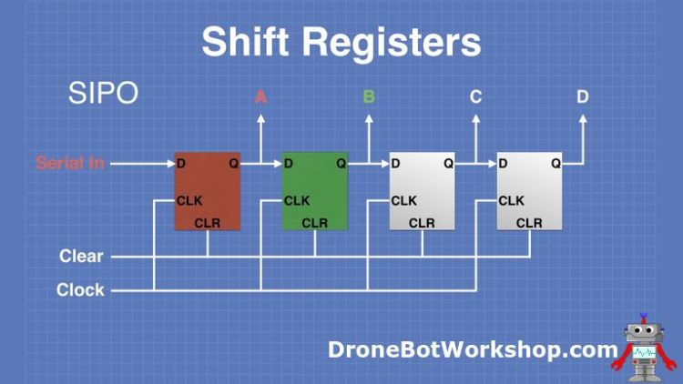
The next bit of data pushes the original bit over to the next flip-flop.
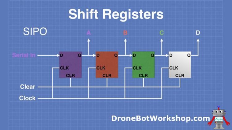
This process continues as the serial data is clocked in. Note that the flip-flop only updates the input value when it is clocked.
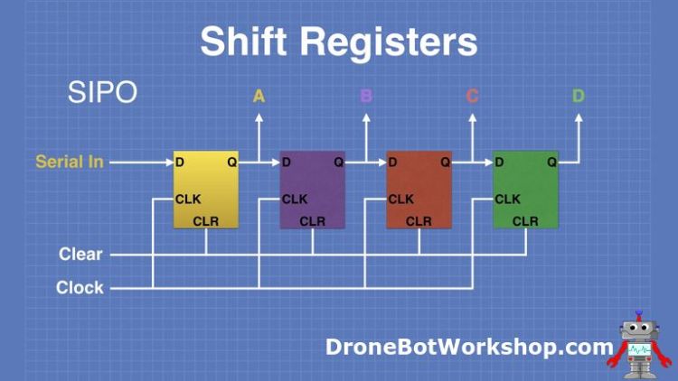
Finally when all the data is clocked in the parallel output can be read. In most shift registers an extra buffer holds the parallel data and doesn’t change it until all the dat ais clocked in.
A PISO, or Parallel In – Serial Out shift register is constructed as follows
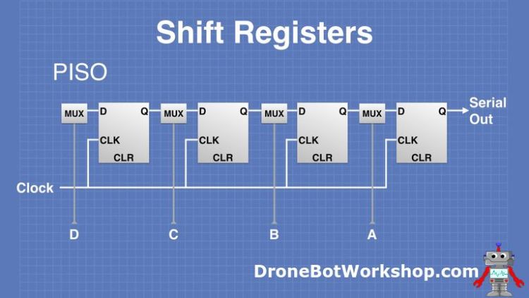
The “MUX” section of this diagram actually consists of a number of discrete logic gates, and they serve to feed the data into their associated flip-flop at the correct time.
This is important as a PISO shift register needs to clock each bit of the parallel data individually. This means that the data on the parallel input can’t change while it is being read, again most practical designs employ a buffer to hold the parallel data.
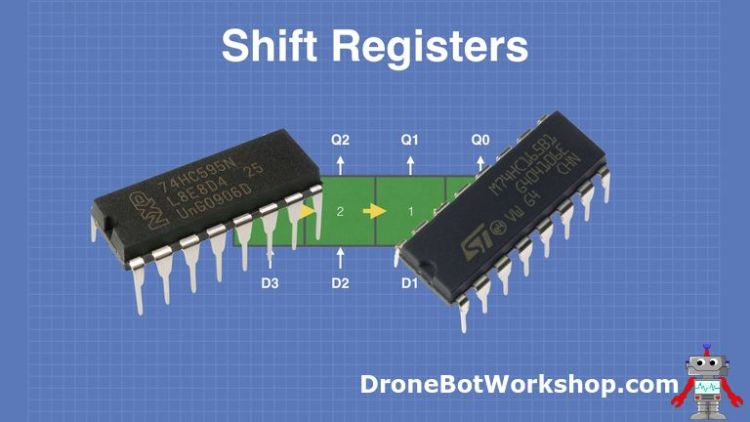
Cascading Shift Registers
A shift register is cataloged by the number of bits it handles, the ones shown in the previous illustrations were 4-bit registers and both of the shift registers that we will be using today are 8-bit devices.
If you need to increase the amount of parallel data you can handle with a shift register you can cascade it with another shift register. So two 8-bit shift registers can support 16-bits, add another one for 24-bits, etc.
You don’t need additional connections to the microcontroller to cascade shift registers, so it’s a great way to drive a lot of LEDs or read a lot of switches without using up a lot of ports.
74HC575 & 74HC165 Shift Registers
We will be using two very common and easily obtained shift registers today, the 74HC595 SIPO and 74HC165 PISO. Let’s take a closer look at these chips.
74HC595 – 8-bit Serial In – Parallel Out
The 74HC575 is an 8-stage serial shift register that also has an internal storage register. The storage register buffers the output data and can be clocked independently of the shift register. This prevents the data from changing while it is being loaded.
The 74HC595 has a “3-state” output. This means that the pins on the parallel data output can be at three different states.
- LOW
- HIGH
- OFF
The OFF state is a high-impedance state that effectively disconnects the output of the chip. This technique allows several 3-state chips to drive the same bus, with only one of them active at any given time.
The pinout of the 74HC575 in the DIP package is illustrated here:
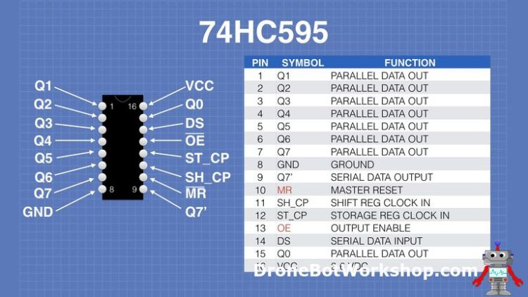
The serial data is input on the DS pin (pin 14). You can use the Q7’ pin to cascade these devices to increase the number of parallel outputs you can control.
The Output Enable (pin 13) controls the 3-state bus, if it is LOW then the output bus is enabled.
74HC165 – 8-bit Parallel In – Serial Out
The 74HC165 is an 8-bit parallel-load shift register which has a serial output. It has complementary outputs, one of which can be tied to another 74HC165 to cascade them.
This device is used for parallel to serial data conversion and has the following pinout:

As with the 74HC595, this is a very common integrated circuit and you should have no trouble obtaining it at almost any electronics supplier.
Extra Output Ports with the 74HC595
We will begin our experiments with the 74HC595 SIPO (Serial In – Parallel Out) shift register.
The 74HC595 allows us to expand the number of digital I/O ports on our Arduino. In these experiments, we will be using it to drive some LEDs, which we will control using an Arduino.
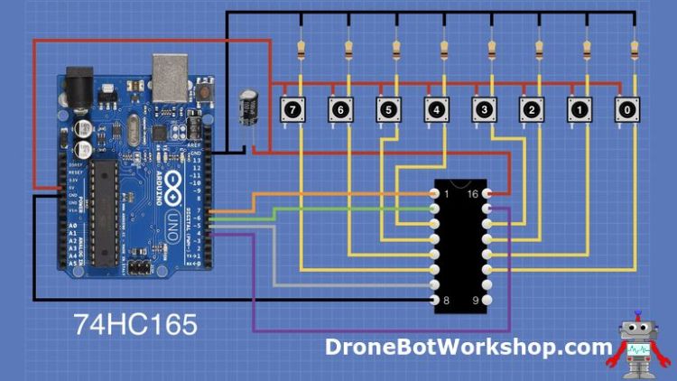
Arduino & 74HC595 Hookup
Here is how we will be hooking up the 74HC595 to an Arduino and to eight LEDs.
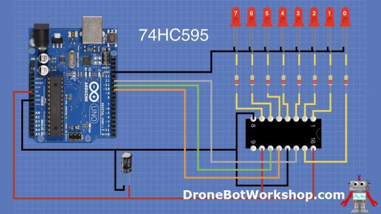
Note the addition of a decoupling capacitor, across the power supply, this is a good idea when working with TTL chips like the 74HC595. I used a 100uf capacitor but any value from 10uf upwards will work just fine. Make sure that you observe the polarity of the capacitor.
On my breadboard, I replaced the eight dropping resistors with an 8×2 220-ohm resistor array. This is a convenient component to have when you need a lot of identical resistors. Of course, you may use discrete resistors if you don’t have an array.
There are a lot of wires here so double-check your wiring. You may test the LED-dropping resistor combos by wiring them first and then applying 5 volts to the resistor, if it is wired correctly you’ll light the LED. Repeat the test for all eight resistor-LED pairs. Do this before you wire up the 74HC595 and the Arduino.
Once it is all wired up you can move forward and write some code to make it all work.
Arduino shiftOut() Function
There are a couple of ways to “talk” to a shift register with an Arduino. One way is to use the SPI bus, which would allow you to make use of existing libraries to simplify writing code.
Another way is to use any standard I/O pins on the Arduino to create a clock and to exchange serial data. This is the method we will employ to work with the 74HC595 shift register.
Arduino provides a shiftOut() function to simplify moving data on a serial connection. It can take a byte value and output it in a serial format in sync with a clock pulse on another pin. You can choose to output the data in two directions.
- MSB First – The Most Significant Bit first. So the binary number 10110010 will output a bit at a time starting with “101”, or from left to right.
- LSB First – The Least Significant Bit first. In this case, the binary number 10110010 will output a bit at a time starting with “010”, or from right to left.
We will make use of this function in our sketch.
Arduino & 74HC595 Sketch
Our sketch is pretty simple. The shiftOut function takes care of sending our data to the shift register and of creating a clock signal.
/*
  74HC595 Shift Register Demonstration 1
  74hc595-demo.ino
  Count in Binary and display on 8 LEDs

  Modified from "Hello World" example by Carlyn Maw,Tom Igoe and David A. Mellis

  DroneBot Workshop 2020
  https://dronebotworkshop.com
*/

// Define Connections to 74HC595

// ST_CP pin 12
const int latchPin = 10;
// SH_CP pin 11
const int clockPin = 11;
// DS pin 14
const int dataPin = 12;

void setup ()
{
  // Setup pins as Outputs
  pinMode(latchPin, OUTPUT);
  pinMode(clockPin, OUTPUT);
  pinMode(dataPin, OUTPUT);
}

void loop() {
  // Count from 0 to 255 and display in binary

  for (int numberToDisplay = 0; numberToDisplay < 256; numberToDisplay++) {

    // ST_CP LOW to keep LEDs from changing while reading serial data
    digitalWrite(latchPin, LOW);

    // Shift out the bits
    shiftOut(dataPin, clockPin, MSBFIRST, numberToDisplay);

    // ST_CP HIGH change LEDs
    digitalWrite(latchPin, HIGH);

    delay(500);
  }
}
This sketch is just an adaptation of one that Arduino provides in their excellent lesson on using the 74HC595 with the Arduino. It uses the eight LEDs as the display for a binary counter.
We begin by assigning variable names to the pins connected to the 74HC595. All of these pins are then set up as outputs. We then move on to the Loop.
We use a for-next loop to count from 0 to 255, incrementing by one. On each increment, we write the counter value out to the shift register. The latch pin is used to hold the data until we are ready so that the display doesn’t flicker as the shift register is being loaded.
After a half-second delay, the next number is loaded.
The result is that the LEDs display a binary count from 0 to 255.
You can experiment with the code and manipulate some values and observe the effect on the LEDs. Try changing the MSBFIRST parameter in the shiftOut statement to LSBFIRST and see what happens.
It’s a simple way to understand basic shift register operation.
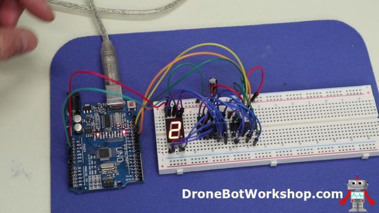
Driving 7-Segment Displays
Another use for the 74HC575 is to drive a 7-segment LED display. You can use it to red=uce the number of connections to one display, or you can cascade multiple 74HC595s to drive several displays.
7-Segment LED Displays
A typical 7-segment LED display layout is shown here:

Note that there are actually eight LED elements in a “7-Segment” display, the eighth LED is used as a decimal point. In some displays, this may be substituted with a colon.
LED displays are available in two configurations:
- Common Anode – All the LEDs are connected with a common Anode (positive) connection.
- Common Cathode – All the LEDs are connected with a common Cathode (negative) connection.
Both display types use the same pinout, so it is very important to know what type you have. A good way to tell (other than referencing the display part number) is to use a multimeter on the “diode test” function. When connected with the proper polarity it can be used to light the LED elements.
The Common Cathode display is more common and is the type we will be using for our experiment.
74HC595 7-Segment Display Hookup
As the Common Cathode 7-segment LED display is really just eight LEDs connected to a common cathode( (negative) terminal it is no different than the eight LEDs we used in our first experiment. So we can use the exact same circuit to hook it up.
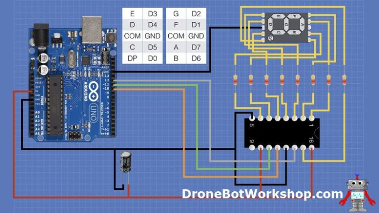
Use the chart in the hookup diagram to connect the display pins to the dropping resistors. The COM pin (the Common Cathode) is connected to the Arduino’s Ground. Note that the display will have two COM pins, you only need to connect one.
Once you have that all hooked up you can test it by running the previous sketch, which should test all the LED segments including the decimal point.
But to actually display something coherent we will need a different sketch.
74HC595 7-Segment Display Sketch
Here is the sketch we will use to test out our 7-segment display.
/*
  74HC595 Shift Register with 7-segment LED display
  74hc595-7segdisplay.ino
  Count in hex from 0-F and display on 7-segment Common Cathode LED display

  DroneBot Workshop 2020
  https://dronebotworkshop.com
*/

// Define Connections to 74HC595

// ST_CP pin 12
const int latchPin = 10;
// SH_CP pin 11
const int clockPin = 11;
// DS pin 14
const int dataPin = 12;

// Patterns for characters 0,1,2,3,4,5,6,7,8,9,A,b,C,d,E,F
int datArray[16] = {B11111100, B01100000, B11011010, B11110010, B01100110, B10110110, B10111110, B11100000, B11111110, B11110110, B11101110, B00111110, B10011100, B01111010, B10011110, B10001110};

void setup ()
{
  // Setup pins as Outputs
  pinMode(latchPin, OUTPUT);
  pinMode(clockPin, OUTPUT);
  pinMode(dataPin, OUTPUT);
}
void loop()
{
  // Count from 0 to 15
  for (int num = 0; num < 16; num++)
  {
    // ST_CP LOW to keep LEDs from changing while reading serial data
    digitalWrite(latchPin, LOW);

    // Shift out the bits
    shiftOut(dataPin, clockPin, MSBFIRST, datArray[num]);

    // ST_CP HIGH change LEDs
    digitalWrite(latchPin, HIGH);

    delay(1000);
  }
}
This sketch has many similarities to the previous one, which isn’t surprising when you consider that it does pretty well the same thing.
We start again by defining our connections to the 74HC595.
Then we create an array with 16 elements, each one representing the pattern for a character to display on the 7-segment LED.
The elements are written in binary and it makes it simple to understand how they work. Within the binary byte, each bit represents one of the LED segments. From MSB to LSB (left to right) they represent the following segments in the display:
a – b – c – d – e – f – g – DP
When the bit is set to “1” the LED segne=nt is on, a “0” means it is off.
The array is ordered so element 0 is the character for “0”. Element 1 is the character for “1” etc. It is in hexadecimal so element 15 is “F”.
Look at the array elements and you’ll see the pattern.
Once again in Setup, we set our connections as outputs and then move onto the Loop.
Again we use a counter, only this time ist is between 0 and 15. We will display these values as they are counted on the LED display in Hexadecimal format.
We step through the array one element at a time, using shiftOut to send the element data to the shift register.
Load up the code and observe the display. If everything is connected correctly you’ll see it count from 0 to F and then repeat.
Extra Input Ports with the 74HC165
Now that we have seen how to add output ports with a shift register it’s time to do the opposite and add some inputs. For that job, we will use the 74HC165.
We will use the 74HC165 shift register along with eight momentary-contact pushbutton switches. The shift register will take the 8 inputs from the switch and send them to the Arduino as serial data.
Arduino shiftIn() Function
Once again Arduino has a dedicated function for receiving serial data.
The shiftIn() function shifts serial data in one byte at a time. It can be set to take the MSB or LSB first. It is often used with a shift register like the 74HC165 or the CD4021BE.
As with its cousin the shiftOut function the shiftIn function also supplies a clock signal to synchronize the data transmission.
Arduino & 74HC165 Hookup
The inputs of the 74HC165 need to be pulled down LOW to prevent false readings, so in addition to our eight pushbutton switches we will also need eight pulldown resistors. I used 10k resistors, but any value from 4.7k to 27k will work fine.
Once again I used a 100uf decoupling capacitor, make sure you observe the polarity when connecting this.
Once you have it all hooked up we can focus on the sketch we will be using to make this work.
Arduino & 74HC165 Sketch
Our sketch is very simple, as all it does is read the status of the pushbuttons and display the results on the serial monitor. But that’s really all you need to do to understand how to get data from your pushbuttons and the 74HC165.
/*
  74HC165 Shift Register Demonstration 1
  74hc165-demo.ino
  Read from 8 switches and display values on serial monitor

  DroneBot Workshop 2020
  https://dronebotworkshop.com
*/

// Define Connections to 74HC165

// PL pin 1
int load = 7;
// CE pin 15
int clockEnablePin = 4;
// Q7 pin 7
int dataIn = 5;
// CP pin 2
int clockIn = 6;

void setup()
{

  // Setup Serial Monitor
  Serial.begin(9600);

  // Setup 74HC165 connections
  pinMode(load, OUTPUT);
  pinMode(clockEnablePin, OUTPUT);
  pinMode(clockIn, OUTPUT);
  pinMode(dataIn, INPUT);
}

void loop()
{

  // Write pulse to load pin
  digitalWrite(load, LOW);
  delayMicroseconds(5);
  digitalWrite(load, HIGH);
  delayMicroseconds(5);

  // Get data from 74HC165
  digitalWrite(clockIn, HIGH);
  digitalWrite(clockEnablePin, LOW);
  byte incoming = shiftIn(dataIn, clockIn, LSBFIRST);
  digitalWrite(clockEnablePin, HIGH);

  // Print to serial monitor
  Serial.print("Pin States:\r\n");
  Serial.println(incoming, BIN);
  delay(200);
}
The sketch starts out like all of our previous sketches, defining the four connections to the IC.
In the Setup, we initialize the serial monitor and then set the connections up as required.
In the Loop, we first write a pulse to the load pin, which will have it load the data from its parallel input into a buffer to be worked on.
Next, we set up the 74HC165 to prepare to send data and then use the shiftIn function to get that data, LSB (Least Significant Bit) first. We finish by taking the clock pin HIGH, signifying we are done.
Finally, we print the result to the serial monitor.
Load the sketch, open your serial monitor and observe the output. Right away you’ll notice something.
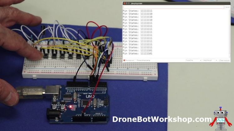
The data is all held HIGH on the output, the opposite of what is wired on the board. Pressing a pushbutton will cause it to read LOW, even though that is the opposite of what is really happening.
This is because we are using the complementary output from the 74HC165. Our data is inverted.
I’ll show you in a later sketch how to turn it back the right way around. Keep on reading!
The example we just used has many practical applications, one of the obvious ones is as a keypad (although there are better ways to make a large keypad). For a project that requires a lot of switches, it is a useful design technique.
One great application of this circuit is to use it with DIP switches or jumpers, ones that are only occasionally set. You can use the 74NC165 to reduce the number of connections required to read an 8-position DIP switch, and just read it in the Setup routine so it is only read when the device is powered on or reset.
Using the 74HC595 and 74HC165 Together
Of course, it would be a shame to have wired up all of those LEDs and switches without going the extra step to connect them together! So let’s do exactly that.
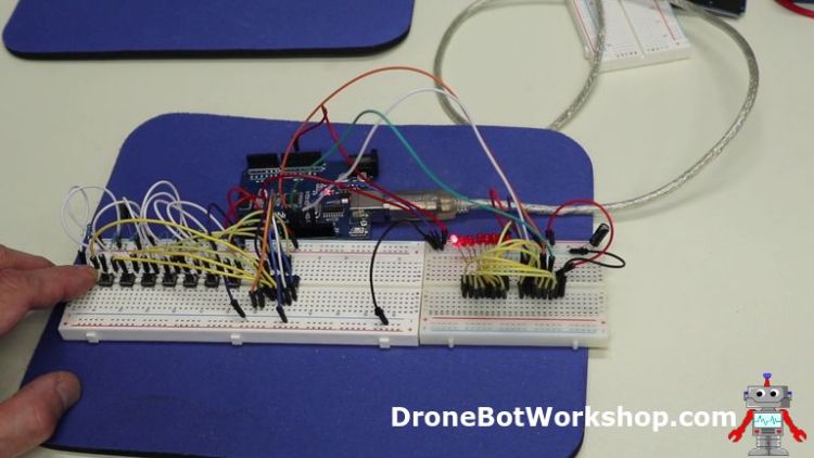
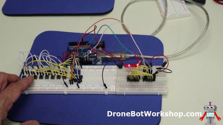
74HC595 and 74HC165 Hookup
If you built each of the demonstrations on its own solderless breadboard as I did then hooking both of them together is very simple.
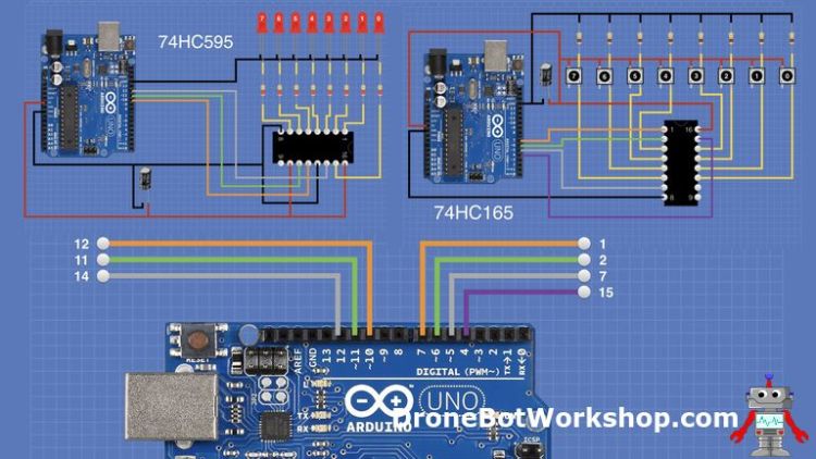
Disconnect the Arduino from its breadboard on one of the demonstrations, it doesn’t really matter which one. Leave the connections on the breadboard so that you can reconnect them to the other Arduino. You can connect the 5-volt and Ground connections to the other breadboards power rails.
When you are done try running the previous sketches on the Arduino, everything should still work. If something doesn’t work then check your wiring, something might have become disconnected when you joined the projects – there are a lot of wires here!
Once you have everything tested it’s time to look at a sketch to use both the 74HC165 and 74HC595 together.
74HC595 and 74HC165 Sketch 1 – Boring!
As our demo is essentially two demos fused together our sketch is pretty well the same thing. You’ll see a lot of similarities between this sketch and the previous ones, and it’s no accident – some of it is literally cut and paste!
The purpose of the sketch is to simply use the LEDs to display the status of the pushbuttons. Really boring, and a complete waste of a microcontroller and some shift registers, but as a demonstration, it works well. I promise we’ll move on to something more exciting after this!
/*
  74HC595 & 74HC165 Shift Register Demonstration
  74hc595-to-74ch165.ino
  Input for 8 pushbuttons using 74HC165
  Output to 0 LEDs using 74HC595

  DroneBot Workshop 2020
  https://dronebotworkshop.com
*/

// Define Connections to 74HC165

// PL pin 1
int load = 7;
// CE pin 15
int clockEnablePin = 4;
// Q7 pin 7
int dataIn = 5;
// CP pin 2
int clockIn = 6;

// Define Connections to 74HC595

// ST_CP pin 12
const int latchPin = 10;
// SH_CP pin 11
const int clockPin = 11;
// DS pin 14
const int dataPin = 12;

void setup () {

  // Setup Serial Monitor
  Serial.begin(9600);

  // 74HC165 pins
  pinMode(load, OUTPUT);
  pinMode(clockEnablePin, OUTPUT);
  pinMode(clockIn, OUTPUT);
  pinMode(dataIn, INPUT);

  // 74HC595 pins
  pinMode(latchPin, OUTPUT);
  pinMode(clockPin, OUTPUT);
  pinMode(dataPin, OUTPUT);

}


void loop() {

  // Read Switches

  // Write pulse to load pin
  digitalWrite(load, LOW);
  delayMicroseconds(5);
  digitalWrite(load, HIGH);
  delayMicroseconds(5);

  // Get data from 74HC165
  digitalWrite(clockIn, HIGH);
  digitalWrite(clockEnablePin, LOW);
  byte incoming = shiftIn(dataIn, clockIn, LSBFIRST);
  digitalWrite(clockEnablePin, HIGH);

  // Print to serial monitor
  Serial.print("Pin States:\r\n");
  Serial.println(incoming, BIN);


  // Write to LEDs

  // ST_CP LOW to keep LEDs from changing while reading serial data
  digitalWrite(latchPin, LOW);

  // Shift out the bits
  shiftOut(dataPin, clockPin, LSBFIRST, ~incoming);

  // ST_CP HIGH change LEDs
  digitalWrite(latchPin, HIGH);

  delay(500);

}
We stare by once again defining pin connections to both integrated circuits. And in the Setup, we initialize the serial monitor and set the connections up as required.
The Loop starts with the same routine we used earlier to read the pushbutton values from the 74HC165. Again we insert the data into an 8-bit byte called “incoming” and display its value on the serial monitor.
Next, we use the same code we used earlier to write the data to the 74HC595. But we make one change to the date we send to the shift register.
Remember, our data from the switch is inverted. If we send it to the 74HC595 it will work, but the LEDs will all be on, except where we have pressed a pushbutton.
To invert the date we use the “~” symbol in front of the “incoming” variable when we use it in the shiftOut function. The tilde (squiggly) symbol inverts the binary data, turning every zero into a one and vice versa. Exactly what we need to do.
You’ll also notice that one thing we do differently from the earlier 74HC595 sketch is we send the data LSB first. This matches how we receive it from the pushbuttons. Sending it MSB first would work, but the LED display would be reversed.
Load it up and try it out.
Thrilling, isn’t it?
OK, it really isn’t, but it does show how you can take parallel data (the switch inputs), convert it to serial with a shift register, send it to an Arduino, send it back out to a second shift register and convert it back into parallel again (the LED outputs). And that’s sort of thrilling.
If you aren’t completely thrilled then don’t worry, we can do other things now that we have eight switches and eight LEDs.
74HC595 and 74HC165 Sketch 2 – Exciting!
To add some excitement to our demo let’s use the eight switches to select LED light flashing patterns. As we have eight switches we can select eight patterns.
Here is how we will do it:
/*
  74HC595 & 74HC165 Shift Register Demonstration 2
  74hc595-to-74ch165-pattern.ino
  Input from 8 pushbuttons using 74HC165
  Output to 8 LEDs using 74HC595

  Select LED pattern using pushbuttons

  DroneBot Workshop 2020
  https://dronebotworkshop.com
*/
// Define Connections to 74HC165

// PL pin 1
int load = 7;
// CE pin 15
int clockEnablePin = 4;
// Q7 pin 7
int dataIn = 5;
 // CP pin 2
int clockIn = 6;

// Define Connections to 74HC595

// ST_CP pin 12
const int latchPin = 10;
// SH_CP pin 11
const int clockPin = 11;
// DS pin 14
const int dataPin = 12;

// Define data array
int datArray[8];

void setup () {

// Setup Serial Monitor
Serial.begin(9600);

// 74HC165 pins
pinMode(load, OUTPUT);
pinMode(clockEnablePin, OUTPUT);
pinMode(clockIn, OUTPUT);
pinMode(dataIn, INPUT);

// 74HC595 pins
pinMode(latchPin,OUTPUT);
pinMode(clockPin,OUTPUT);
pinMode(dataPin,OUTPUT);

}


void loop() {

// Read Switches

// Write pulse to load pin
digitalWrite(load,LOW);
delayMicroseconds(5);
digitalWrite(load,HIGH);
delayMicroseconds(5);

// Get data from 74HC165
digitalWrite(clockIn,HIGH);
digitalWrite(clockEnablePin,LOW);
byte incoming = shiftIn(dataIn, clockIn, LSBFIRST);
digitalWrite(clockEnablePin,HIGH);

// Print to serial monitor
Serial.print("Pin States:\r\n");
Serial.println(incoming, BIN);

// Setup array for LED pattern

switch (incoming) {

  case B11111110:

    datArray[0] = B11111111;
    datArray[1] = B01111110;
    datArray[2] = B10111101;
    datArray[3] = B11011011;
    datArray[4] = B11100111;
    datArray[5] = B11011011;
    datArray[6] = B10111101;
    datArray[7] = B01111110;

    break;

  case B11111101:

    datArray[0] = B00000001;
    datArray[1] = B00000010;
    datArray[2] = B00000100;
    datArray[3] = B00001000;
    datArray[4] = B00010000;
    datArray[5] = B00100000;
    datArray[6] = B01000000;
    datArray[7] = B10000000;

    break;

  case B11111011:

    datArray[0] = B10000001;
    datArray[1] = B01000010;
    datArray[2] = B00100100;
    datArray[3] = B00011000;
    datArray[4] = B00000000;
    datArray[5] = B00100100;
    datArray[6] = B01000010;
    datArray[7] = B10000001;

    break;


  case B11110111:

    datArray[0] = B10101010;
    datArray[1] = B01010101;
    datArray[2] = B10101010;
    datArray[3] = B01010101;
    datArray[4] = B10101010;
    datArray[5] = B01010101;
    datArray[6] = B10101010;
    datArray[7] = B01010101;

    break;


  case B11101111:

    datArray[0] = B10000000;
    datArray[1] = B00000001;
    datArray[2] = B01000000;
    datArray[3] = B00000010;
    datArray[4] = B00100000;
    datArray[5] = B00000100;
    datArray[6] = B00010000;
    datArray[7] = B00001000;

    break;

  case B11011111:

    datArray[0] = B11000000;
    datArray[1] = B01100000;
    datArray[2] = B00110000;
    datArray[3] = B00011000;
    datArray[4] = B00001100;
    datArray[5] = B00000110;
    datArray[6] = B00000011;
    datArray[7] = B10000001;

    break;

 case B10111111:

    datArray[0] = B11100000;
    datArray[1] = B01110000;
    datArray[2] = B00111000;
    datArray[3] = B00011100;
    datArray[4] = B00001110;
    datArray[5] = B00000111;
    datArray[6] = B10000011;
    datArray[7] = B11000001;

    break;

 case B01111111:

    datArray[0] = B10001000;
    datArray[1] = B01000100;
    datArray[2] = B00100010;
    datArray[3] = B00010001;
    datArray[4] = B10001000;
    datArray[5] = B01000100;
    datArray[6] = B00100010;
    datArray[7] = B00010001;

    break;

  default:

    break;

  }

// Write to LEDs

// Count from 0 to 7
  for(int num = 0; num < 8; num++)
  {
    // ST_CP LOW to keep LEDs from changing while reading serial data
    digitalWrite(latchPin, LOW);

    // Shift out the bits
    shiftOut(dataPin,clockPin,MSBFIRST,datArray[num]);

    // ST_CP HIGH change LEDs
    digitalWrite(latchPin, HIGH);

    delay(200);
  }

}
As you can see I’ve once again borrowed coded from all of the previous demos. In fact, there is really only one thing different about this sketch, and that’s the switch-case statement that allows you to select the LED patterns.
We use the ”incoming” byte, which holds the switch values, as the switch for the statement. Then we have eight cases, one for each switch press. You could probably add more if you wanted to allow for pressing two buttons simultaneously, but eight was enough for me!
In each case section, we populate the datArray array with LED patterns, written in binary so they are easy to see. In each byte, a “1” represents an LED that is illuminated, whereas “0” indicates the LED is off.
I used eight elements in the array to make it easier, but you can increase this to any number you like. Just change the number in the array definition and in the for-next loop that cycles through the array elements.
I set the delay between pattern changes to 200ms, but you can change that. Even better, try putting the delay as a variable in each case evaluation, so you can make the patterns run at different speeds.
The sketch runs as advertised, and it’s actually a lot of fun to watch.
You could improve on the sketch by cascading the 74HC595 to add more LEDs. You could also make the speed variable by adding a potentiometer to one of the analog inputs and using it to set the delay time. And the enable input on the 74HC595 can be driven with PWM to change LED intensity, which you could control with a second potentiometer.
You could even add some MOSFETs to drive larger LEDs and make your own marquis!
A simple demo with lots of potential.
Conclusion
Shift registers may be elementary building blocks that might seem out of place aside microcontrollers and other more capable chips, but they still can perform important functions in a modern design. They can be very useful if you need to add extra inputs or outputs to your project, they are inexpensive and easy to use.
Nothing shifty about that!
Resources
Code for this Article – All of the sketches used in this article in an easy-to-use ZIP file.
PDF Version – The article in a printable PDF format.
74HC165 Datasheet – The specs for the 74HC165.
74HC595 Datasheet – The 74HC595 shift register specs.
Related
Arduino Visual Programming - Getting Started with XODMarch 30, 2018
In "Arduino"
Using LCD Displays with ArduinoMarch 19, 2018
In "Arduino"

From Arduino Uno to ATmega328 - Shrinking your Arduino ProjectsDecember 29, 2018
In "Arduino"
Summary
Article Name
Shift Registers - 74HC595 & 74HC165 with Arduino
Description
Learn to use the 74HC595 and 74HC165 shift registers to add extra input and output ports to your Arduino. We will see how these simple devices work and how to use them to build a fancy LED light display with eight different flashing patterns.
Author
DroneBot Workshop
Publisher Name
DroneBot Workshop
Publisher Logo

'사물인터넷' 카테고리의 다른 글
| Controlling AC Devices with Arduino (0) | 2021.07.04 |
|---|---|
| Meet the Seeeduino XIAO (0) | 2021.07.04 |
| Measure DC Voltage and Current with an Arduino (0) | 2021.07.04 |
| xno-6085ra (0) | 2021.01.23 |
| Mikrotik ssh/telnet/ftp Bruteforce 공격 차단 (0) | 2018.08.20 |


